


isiMotor's Camber Calculations
Every time I take another swing at analysing cars I find myself getting clotheslined by a new tidbit of the inner machinations of isiMotor based sims. The latest demon to escape Pandora's box is about camber, which under my old assumptions made a lot less force than it does. Seeing camber suddenly dominating my tyre force calculator for the specific car I was working on got me thinking a little harder about how exactly camber plays with other variables.
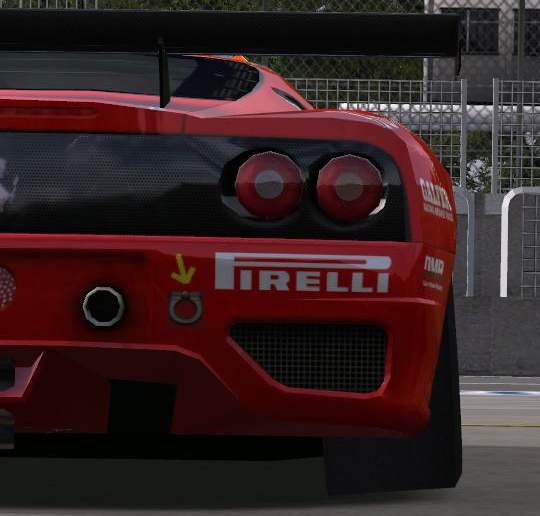
I'm going to, by default, be talking about negative camber (both tyres leaning into the car, as illustrated above). And because sign convention can get a little confusing, if I say more camber, I'm talking about the absolute magintude of the camber, not going more positive (or less negative).
Camber is interesting because of two main aspects:
- It's always producing force, even in a straight line, which you can visualise by putting a cup or a cone on its side and rolling it. It'll turn in the direction of the end with a smaller radius, which is known as camber thrust. If you have negative camber on one side, and positive camber on the other, the car will want to crab in the direction the tyres are leaning.
- In cornering, it has the opposite impact to tyre load sensitivity. The camber thrust on the inside tyre is producing a force against the direction you're turning, and the outside tyre is helping you, so weight transfer is beneficial from the perspective of camber.
The Facts of Fiction
It's horrible that most of the best sims for modding are also built from a black box with relatively little documentation, other than the few notes in the car files, trial and error passed across decades, and whatever Niels Heusinkveld dripfeeds from his time working on Automobilista. This post was ignited from stumbling over this message (Discord Link), but if you don't want to go near Discord, here's a screenshot:
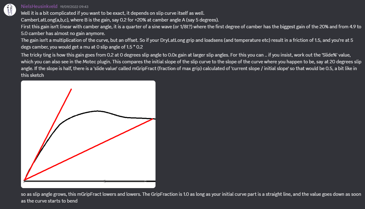
And now I'm going to re-explain that, if nothing else but to try and invoke Cunningham's Law for ways I've potentially misunderstood. Starting with how isiMotor handles getting to peak camber.
//The line in the tyre file of most isiMotor sims
CamberLatLong=(peakCamber, lateralGain, longitudinalLoss)

camberGripImprovement = lateralGain * sin(camber / peakCamber * pi / 2 - 2 * pi)
This produces a curve like this:
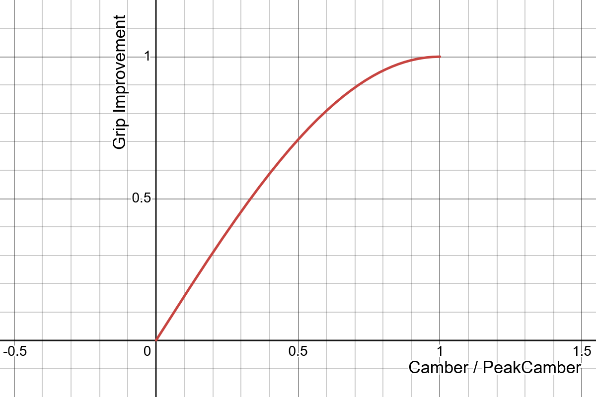
So when the camber on the car is equal to peakCamber defined in the files, you get maximum grip. As you get closer and closer to the peak, the gains get smaller, until you go over the top where, supposedly, the loss in grip is a linear decline all the way to ninety degrees of camber. To get the actual grip added, you take the maximum friction coefficient of the tyre, multiply it by the lateralGain value, and add it on to create an offset, simulating camber thrust.
Except that's not quite it. Grip from camber decays as slip increases (or usually should since, on any tyre following reality, the initial slope should be steepest). The decay is based on slope of the current point in the friction curve the tyre is operating on, divided by the initial slope of the friction curve.
We need a few details from the tyre file for a given car before we can see the impact of the tyre. The friction vs lateral slip curves are also required, under the title of SLIPCURVE in the file. It'll look something like this:
[SLIPCURVE]
Name="LatFront"
Step=0.0033
DropOffFunction=0
Data:
       0
0.341989
0.623587
0.807985
0.914034
0.968341
0.991823
       1
0.999919
0.999836
The important details are the Step value and the Data output for the slip we're looking at. Step is the interval of slip each point in Data is placed, and each point describes how much friction is made. Since 1 is the highest value on that dataset, and it's 7 steps along, peak slip is made at 0.0033 * 7 radians of slip angle. This isn't strictly true because the game redefines peak slip at another point in the files, but that doesn't factor for this part of the process. With this gathered, we can start to fully analyse camber's impact.
//take the slip curve from the tyre file.
initialSlope = SLIPCURVE_Data[1] / SLIPCURVE_Step
//Remember, arrays start at zero

//take the slope to the current slip
currentSlope = SLIPCURVE_Data[i] / (SLIPCURVE_Step * i)
//This is apparently the total slip of the tyre, not just slip angle
//This will focus on pure lateral slip

//camber functions as an offset to the slip angle vs mu curve,
//producing lateral force even when the tyre is rolling straight ahead
currentMu += maximumMu * camberGripImprovement * currentSlope / initialSlope
//where maximumMu is the friction coefficient once all other factors have been included
//such as tyre load sensitivity, the pressure, and temperature
//currentMu is the current friction coefficient of the tyre based on its slip angle
My only question remaining is if camber's decay with slip depends on the curve as defined in the files, as I've included here, or on the actual output curve after it's been modified. The only property that would effect this is the DropOffFunction, which stretches and shrinks part of the curve beyond the peak friction slip angle, so this isn't really crucial, but it would be nice to know. Oh — and it would also be nice to know a decent way to estimate combined slip's impact on lateral grip and camber's effect. I've got theories, but only theories.
isiMotor Optimisations
Knowing the maths, let's see how we might take advantage of this.
More slip means less grip. Since camber weakens with total slip, the earlier peak force slip is made, the more total lateral force you'll see in total. As previously mentioned, peak friction slip can be moved from the initial curve defined in the files, and this is to caputre the effect of load. For a given tyre, the slip where peak force is made usually increases with load and speed.
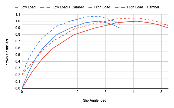
This graph is just a quick mock up of what happens, neglecting tyre load sensitivity, showing how friction coefficient is affected purely from camber's perspective. Despite both tyres starting with 20% of their maximum friction coefficient without camber, by the time they reach the peak, the improvement is closer to 5%, and the tyre with an earlier peak slip benefits more. The earlier the peak is, the more outright grip is made, even though the properties of the tyre are otherwise the same.
This also means that camber changes will make a more significant impact to balance at lower slip angles, in the first and last phases of cornering. As a single example, cranking on rear camber might make a huge improvement to stability, but not cure oversteer. Camber acts strongest initially whereas tyre load sensitivity creates a balance change from load transfer, which has a lag as it depends on the rates of the springs and dampers. Adjusting camber can therefore play a significant part in setting the car into a corner, and have less of an influence on on-limit handling balance. Since camber's performance worsens with total slip, then when it comes to balance changes, flicking into a flat-out kink is probably where camber will have the biggest impact, compared to corners with more braking and accelerating involved.
Negative camber on the inside wheel is working against you, because the camber thrust is aimed in the direction the wheel's leaning, resulting in effective friction coefficients like so:
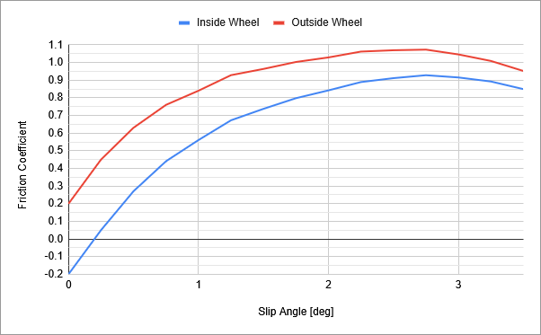
Obviously this is an extreme example that won't literally apply to most practical examples, as we're neglecting weight transfer and any load sensitive effects, but the point still stands. The inside wheel is creating force in the wrong direction completely until it reaches enough slip angle to offset the camber forces. Any way we can weaken its effects would be useful. By intentionally slipping the inside wheel more than necessary (through toe-out or Ackermann steering geometry), we can reduce this detrimental camber. The cars I've analysed so far have (at least on paper) benefited from putting the inside wheel to a higher slip angle than the outside — despite putting that inside tyre past the optimal slip angle according to the curve — because it hurts camber pushing against the direction the car's going in more than the dropoff in friction coefficient past the peak of the curve.
Comparing to Reality
This effect where camber drops off with slip is new to me. Whether this is accurate or not doesn't matter, racing sims are only as good as the data you put in no matter how much maths they do to that data, I just want to know how they work because I enjoy optimising cars. But since the people behind isiMotor went to the effort of modelling this effect, I'll take a lazy look to see if it applies anywhere.
This paper on designing cars for high camber has this graph which shows camber against slip:
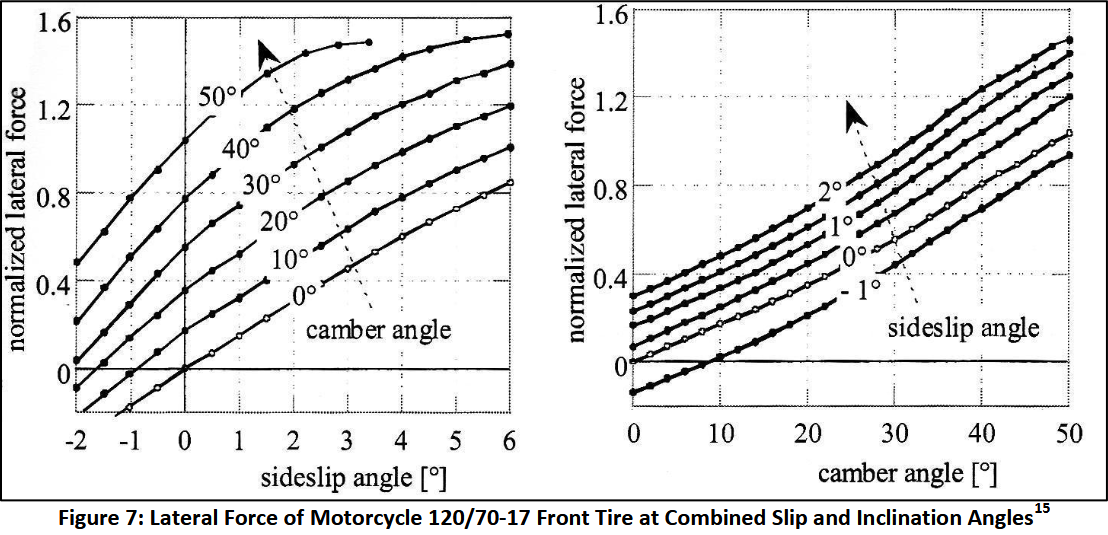
The chart on the left sort of indicates that peak slip occurs earlier with more camber angle, as the higher cambered tyres at 50 and 40 degrees seem to reach a or approach a peak before the limit of the graph, but this is also for a rounded shoulder motorbike tyre. So to look at a more traditonal squared tyre for a car, let's look at real life data from Avon which you can find here (from the sketchiest looking source for tyre data I've ever seen).
There's lateral force data at different loads, and if we look at the ratio of force produced by zero camber and high camber, we can see how great the difference in force is. If camber does drop off with slip, the ratio should apporoach one with slip angle.
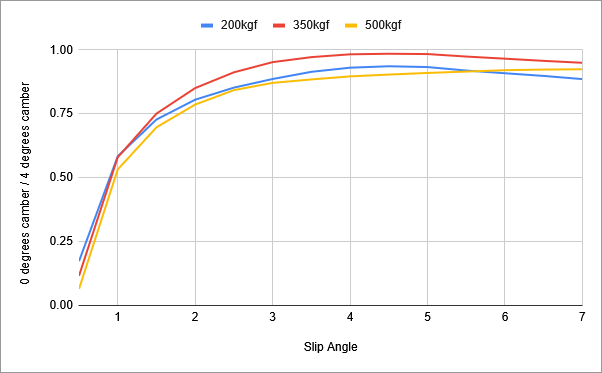
The y-axis is the lateral force at zero camber divided by the lateral force at four degrees of camber, shown across seven degrees of slip angle and at three different loads, for the rear tyre of an early 2000s British F3 car. At y=1, the lateral force is equal at both camber levels, and at y=0.1, the four degrees of camber is making ten times the lateral force of zero dergees. The tyre makes the most force at all loads in this dataset at seven degrees of slip, and four degrees of camber. On the heaviest loaded tyre, the gain from camber shrinks as slip increases, reflecting the isiMotor behaviour, but this isn't shown at the lighter loads. So there's not great correlation to reality, but this is only one dataset so all I can really do with confidence is shrug my shoulders.
I actually have a lot more I can say about camber. There's a thousand words I culled from this trying to figure out the scope of this post because camber is incredibly interesting, especially around edge cases. Expect more from this.